TECHNICAL SPECIFICATION • GYRO COMPASS
TOKIMEC / TOKYO KEIKI
TG-6000 SERIES
Tokimec / Tokyo Keiki TG-6000 Gyro Compass: Core PCBs, Architecture & Technical Troubleshooting Guide
A detailed marine engineering analysis of the Tokimec / Tokyo Keiki TG-6000 marine gyrocompass system. Comprehensive reference of internal printed wiring boards (PWBs / PCBs), dedicated manufacturer part numbers, control loop architecture, voltage drop diagnostic methods, and board failure vs. sensor fault isolation workflows.
Tokimec Inc. / Tokyo Keiki
MCU 101695052 / 10169505
SCU / PMCU 101695282

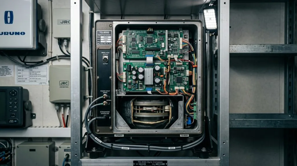
Figure 1: Tokimec / Tokyo Keiki TG-6000 Gyro Compass Master Unit with electronics service bay open, displaying the MCU board, Inverter board, motor driver stage, and sensitive gyrosphere chamber.
1. Operational Heritage & TG-6000 System Architecture
The Tokimec / Tokyo Keiki TG-6000 is an established industry-standard marine gyrocompass deployed across ocean-going container vessels, bulk carriers, oil tankers, and naval auxiliaries worldwide. Designed to comply with IMO A.424(XI) and SOLAS Chapter V Regulation 19, the TG-6000 provides continuous true north reference unaffected by ship magnetic deviation or celestial obscuration.
Unlike monolithic compass designs, the TG-6000 architecture segregates sensitive electromechanical elements from bridge display and user interface subsystems:
- Master Compass Unit: Houses the hermetically sealed, fluid-supported gyrosphere, the high-frequency inverter drive stage, the horizontal tracking loop, and the dedicated Microcontroller Unit (MCU PWB). It resides either in a dedicated compass compartment or inside the wheelhouse console base.
- Control Box / Operation Unit: Positioned on the bridge console, housing the System Control Unit (SCU / PMCU PWB). It presents digital heading displays, system status enunciators, latitude/speed error correction input keypads, and historical fault log registers.
- Transmission & Repeater Interfaces: Drives multi-channel RS-422 NMEA 0183 heading sentences (
$HEHDT,$THS,$HEROT), step signals, and synchro lines to bridge radars, ECDIS, autopilot steering stands, VDR, and bridge wing bearing repeaters.
2. Core Printed Wiring Boards (PWBs / PCBs) & Part Numbers
Reliable maintenance, component-level troubleshooting, and emergency marine electronics attendance require exact identification of the modular printed wiring boards installed within the TG-6000 chassis. Below is the authoritative manufacturer part number directory:
| Board Designation | Dedicated Part Number | Hardware Sub-Assembly | Functional Role & Signal Dynamics |
|---|---|---|---|
| MCU PWB | 101695052 (10169505 series) |
Master Compass Electronics Bay | Main micro-controller board for the master compass. Manages internal sensor signal processing, astronomical north heading calculations, coordinates horizontal leveling (DST), and directs azimuth step motor follow-up actuators. |
| SCU PWB | 101695282 (PMCU assembly) |
Control Box / Operation Panel | System Control Unit CPU. Drives the digital LED/LCD display, processes operator keypad commands, handles repeater transmission timing, and logs real-time error codes and historical fault abnormalities. |
| Inverter PCB | 10169537 (or 1016953) |
Master Compass Lower Bay | Power conversion board. Converts input supply power to high-frequency, regulated 3-phase AC to spin the gyro rotor at operational RPM while monitoring over-voltage, phase drop, and over-current protection circuits. |
| STMD PCB | 10169501 (or 101695012) |
Follow-Up Drive Assembly | Stepping motor driver control board. Amplifies pulse sequences from the MCU to energize the azimuth stepping motor, keeping the follow-up ring aligned with the gyrosphere without mechanical lag. |
| HRZC PCB | 10169503 | Tilt & Leveling Assembly | Horizontal/azimuth tracking reference and control loop circuitry. Monitors electrolytic level sensors to maintain the sensitive sphere parallel to the horizon during vessel rolls and pitches. |
| DGM-60 PCB | 101695075 | Digital Gyro Monitor Unit | System interface module driving serial communication buses and transmission protocols (IEC 61162-1 / NMEA 0183) to bridge equipment such as ECDIS, ARPA radar, and autopilot consoles. |
| Terminal Board | 10169542 | I/O Termination Frame | Standard TG-6000 I/O distribution frame hosting hardwired marine terminal connections for AC/DC power lines, safety ground, alarm relays, and external repeater tracking loops. |
| OPT PCB | 10169509 | Extension Slot Bay | Optional I/O expansion board populated for secondary signal expansion, additional synchro/step outputs, or specialized auxiliary telemetry requirements. |
3. Core Board Functional Breakdown & Circuit Interaction
The high accuracy of the TG-6000 depends on tightly coupled feedback between power generation, tilt leveling, and pulse-driven azimuth tracking:
MCU PWB (101695052 / 10169505)
The neurological hub of the master compass. It samples pickoff voltages from the gyrosphere tilt sensor, calculates true north drift damping based on ship latitude and speed inputs, and generates high-speed quadrature step pulses for the STMD board.
Inverter PCB (10169537 / 1016953)
Powers the high-inertia rotor at extreme RPM inside the sensitive sphere. Incorporates discrete power switching MOSFETs/IGBTs, inductive filtering, and rapid-response thermal shutoffs to protect the rotor against voltage spikes and brownouts.
SCU / PMCU PWB (101695282)
Operates the wheelhouse user console. Maintains constant serial polling with the MCU board. If serial synchronization is lost, the SCU triggers audible and visual bridge alarm enunciations and records the anomaly in non-volatile EEPROM.
4. Technical Diagnostics: Board Failure vs. Sensor Fault Isolation
When troubleshooting a TG-6000 alarm, marine electrical officers and field service technicians must isolate whether the fault originates in a printed circuit board component, a voltage drop across wiring, or an electromechanical sensor failure:
TG-6000 Alarm & Diagnostic Matrix:
Symptom: Control Box indicates inverter fault or rotor speed deviation; inverter LED indicators show trip condition.
Isolation Step 1 (Voltage Verification): Measure the DC/AC primary rail into the Inverter PCB (10169537). Verify supply remains within nominal rating under load.
Isolation Step 2 (Board vs. Sensor/Sphere): Disconnect output harness leading to the gyrosphere slip rings. Measure 3-phase winding resistance through the master compass neck. If phases show balanced resistance (approx. equal impedance) and no short-to-ground, the fault resides on the Inverter PCB switching transistors. If winding impedance is open or shorted, the sensitive element must be replaced.
Symptom: Gyrosphere spins normally but heading card fails to follow vessel yaw, or step motor oscillates rapidly without torque.
Isolation Step 1: Inspect the STMD PCB (10169501) output phase voltages during manual heading slew.
Isolation Step 2 (Mechanical vs. Electrical): De-energize the system and manually rotate the azimuth phantom ring. If high mechanical resistance is felt, inspect the reduction gears, drive pulley (101600291), and drive belt (101600300). If mechanical rotation is smooth, test pulse train outputs from MCU PWB (101695052) pin headers to verify whether the CPU is transmitting drive pulses to the STMD driver.
Symptom: Compass card drifts excessively in rough seas; tilt error alarm displayed on SCU.
Isolation Step: Check the HRZC PCB (10169503). Measure the differential AC pickoff excitation across the horizontal tilt sensor. If excitation voltage is absent, HRZC oscillator circuitry has failed. If excitation is healthy but output voltage does not change linearly when gently tilting the gimbal by hand, the electrolytic tilt pickoff or damping liquid inside the sphere housing requires service.
Symptom: Control Box panel displays communication error; master compass operating status cannot be queried.
Isolation Step: Inspect the RS-422 differential transceiver ICs on both the MCU (101695052) and SCU / PMCU (101695282) boards. Test transmission lines on Terminal Board (10169542) for line continuity, shield grounding, and absence of induced 50/60Hz AC noise from nearby heavy power cables.
5. Sensitive Element Overhaul & Damping Liquid Replacement
The physical heart of the TG-6000 is the gyrosphere sensitive element. Even with immaculate circuit boards, improper electrolyte chemistry or worn slip-ring brushes will cause catastrophic heading inaccuracy:
Mandatory Periodic Overhaul Standards:
- Supporting & Damping Liquid Renewal: The high-viscosity damping fluid and conductive centering liquid must be drained, container walls rinsed, and fresh chemical solution charged according to manufacturer service hour limits (typically every 12 to 24 months).
- Slip Ring & Brush Assembly Inspection: The upper and lower brush assemblies (Part Number references: 101600291, 101600300) transfer 3-phase power into the floating sphere. Worn carbon-silver brushes cause micro-arcing, corrupting inverter wave profiles and generating spurious motor alarms.
- Gimbal Zero-Clearance Balancing: After sensitive element installation, precision balancing weights are adjusted to eliminate static and dynamic imbalance, ensuring settling time remains under 3.5 hours from a cold start.
- Annual Survey Pre-Checks: Class surveyors require verification of emergency power changeover, repeater synchronization within ±0.5°, and error log review from the SCU display.
6. Workshop Diagnostics & Bench Testing at Seanav Marine
At our technical headquarters in Dubai Maritime City (DMC), Seanav Marine maintains specialized test benches and component-level diagnostic instruments for Tokimec and Tokyo Keiki gyrocompass systems:
- Automated PCB Testing: Static bench testing of MCU, Inverter, and STMD boards with dedicated test rigs to measure logic clock stability, PWM inverter firing angles, and thermal drift under sustained electrical load.
- Turn-Table Rate-of-Turn Verification: Reconditioned master compasses are mounted on our precision rotary test bed to measure dynamic follow-up performance up to 30°/second with optical encoder verification.
- Immediate Bonded Inventory: Seanav maintains verified, reconditioned TG-6000 and TG-8000 circuit boards (MCU 101695052, SCU 101695282, Inverter 10169537, STMD 10169501), sensitive elements, and supporting consumables ready for immediate dispatch.
Frequently Asked Technical Questions (FAQ)
Can a damaged Inverter PCB (10169537) damage the gyrosphere?
Yes. If an inverter switching transistor fails in a continuous shorted state, DC voltage or unbalanced 2-phase excitation may be applied to the rotor windings. This produces rapid overheating of the sensitive element stator, which can permanently break down internal winding insulation. Always isolate the inverter board output when investigating motor trip alarms.
Are TG-6000 boards directly interchangeable with the TG-8000 series?
While certain mechanical hardware and motors are shared, many core electronics—including the MCU and SCU firmware—are specific to the model revision. Certain inverter boards (10169537) can be adapted across select TG-6000/8000 revisions, but part numbers and voltage configurations must be cross-verified before installation.
How can onboard engineers request emergency spare PCB dispatch?
Provide Seanav Marine with the exact alarm code displayed on the SCU panel, the part number stamped on your faulty board (e.g. 101695052, 101695282, 10169537), and your vessel’s upcoming port of call. We provide pre-configured replacement modules with technician dispatch across Dubai, Jebel Ali, Fujairah, Singapore, and worldwide hubs.
Require Tokimec / Tokyo Keiki TG-6000 Service or Spares?
Whether your vessel requires emergency PCB module replacement, sensitive element liquid renewal, step motor overhaul, or annual class gyro compass inspection, Seanav Marine engineers are available 24/7 across UAE, India, and worldwide ports.
Authored by Lead Marine Electronics Engineer & Technical Service Desk
Seanav Marine Technical Services LLC • Specialist navigation bridge electronics, gyrocompass overhaul, and IACS survey coordination from Dubai Maritime City (UAE).

Related Gyro Compass Service resources: Gyro Compass Service hub · GEM Elettronica Polaris FOG-100 Gyro Compass: Solid-State Naval Specs, PCBs & Spares · Alphatron AlphaMidiCourse Mk2 Gyro Compass: Wheelmark Specs, PCBs & Spares Directory · Alphatron AlphaMiniCourse Gyro Compass: Compact Commercial Specs, PCBs & Spares · Teledyne TSS Meridian Surveyor Gyro Compass: High-Precision Hydrographic Specs & Spares · Teledyne TSS Meridian Standard Gyro Compass: DTG Architecture, Specs & Spares Guide